XBee API - Frame Information
This page provides detailed information about the byte allocation within different XBee frames in API 1 (API mode without escapes).
Relevant Frame Types
Section titled “Relevant Frame Types”0x00- Tx (Transmit) Request: 64 bit-address0x08- AT Command0x81- RX (Receive) Packet: 16-bit Address0x88- AT Command Response0x89- Tx (Transmit) Status
All 802.15.4 Frame Types
Section titled “All 802.15.4 Frame Types”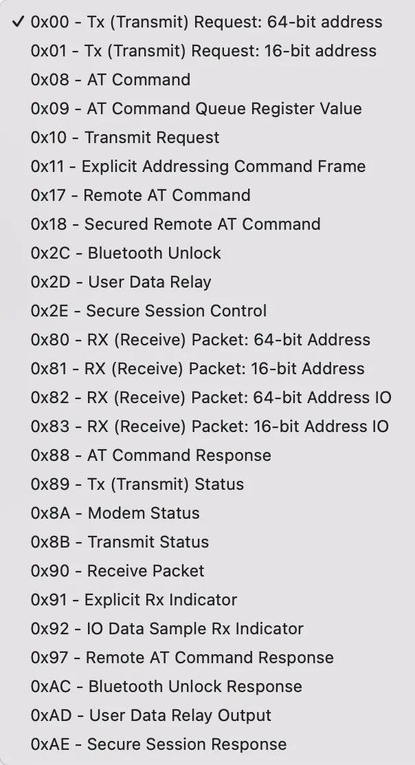
0x00 - Tx (Transmit) Request: 64 bit-address
Section titled “0x00 - Tx (Transmit) Request: 64 bit-address”| Frame Parameters | Bytes |
|---|---|
| Start Delimeter | 1 |
| Length | 2 |
| Frame Type | 1 |
| Frame ID | 1 |
| 64-bit Destination Address | 8 |
| Options | 1 |
| RF Data (Payload) | 0 - 256* |
| Checksum | 1 |
*In practice, maximum payload size is actually 100 bytes
Start Delimiter (1 byte)
Section titled “Start Delimiter (1 byte)”Always set to 7E in XBee API Mode
Length (2 bytes)
Section titled “Length (2 bytes)”Number of bytes between Length and Checksum fields
Frame Type (1 byte)
Section titled “Frame Type (1 byte)”Specefies XBee API frame type (0x00)
Frame ID (1 byte)
Section titled “Frame ID (1 byte)”Identifies the UART data frame for the hose to match with subsequent reqponse. If 0, no response is requested
64-bit Destination Address (8 bytes)
Section titled “64-bit Destination Address (8 bytes)”Set to the 64-bit address of the destination XBee module.
Use 00 00 00 00 00 00 FF FF to send a broadcast packet.
Options (1 byte)
Section titled “Options (1 byte)”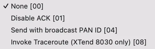
RF Data (0 - 256 bytes)
Section titled “RF Data (0 - 256 bytes)”Packet payload, up to 256 bytes (256 characters)
Checksum (1 byte)
Section titled “Checksum (1 byte)”FF minus 8-bit sum of bytes between length and checksum fields.
0x08 - AT Command
Section titled “0x08 - AT Command”| Frame Parameters | Bytes |
|---|---|
| Start Delimeter | 1 |
| Length | 2 |
| Frame Type | 1 |
| Frame ID | 1 |
| AT Command | 2 |
| Parameter Value | 0 - 256 |
| Checksum | 1 |
Start Delimiter (1 byte)
Section titled “Start Delimiter (1 byte)”Always set to 7E in XBee API Mode
Length (2 bytes)
Section titled “Length (2 bytes)”Number of bytes between Length and Checksum fields
Frame Type (1 byte)
Section titled “Frame Type (1 byte)”Specefies XBee API frame type (0x00)
Frame ID (1 byte)
Section titled “Frame ID (1 byte)”Identifies the UART data frame for the hose to match with subsequent reqponse. If 0, no response is requested
AT Command (2 bytes)
Section titled “AT Command (2 bytes)”Two ASCII characters that identify the AT command.
Parameter Value (0 - 256 bytes)
Section titled “Parameter Value (0 - 256 bytes)”If present, indicates the requested parameter value to set the given register. If no characters are present, get the value of the register.
Checksum
Section titled “Checksum”FF minus 8-bit sum of bytes between length and checksum fields.
0x81 - RX (Receive) Packet: 16-bit Address
Section titled “0x81 - RX (Receive) Packet: 16-bit Address”| Frame Parameters | Bytes |
|---|---|
| Start Delimeter | 1 |
| Length | 2 |
| Frame Type | 1 |
| 16-bit Source Address | 2 |
| RSSI | 1 |
| Options | 1 |
| RF Data | 0 - 100 |
| Checksum | 1 |
Start Delimiter (1 byte)
Section titled “Start Delimiter (1 byte)”Always set to 7E in XBee API Mode
Length (2 bytes)
Section titled “Length (2 bytes)”Number of bytes between Length and Checksum fields
Frame Type (1 byte)
Section titled “Frame Type (1 byte)”Specefies XBee API frame type (0x81)
16-bit Source Address (2 bytes)
Section titled “16-bit Source Address (2 bytes)”16-bit network address of the sender device. Can be set in XTCU (Parameter MM).
Received Signal Strength Indicator (RSSI) (1 byte)
Section titled “Received Signal Strength Indicator (RSSI) (1 byte)”Hexadecimal equivalent of (-dBm) value.
Example:
- For a RX signal strength of -40 dBm, a 28 hexadecimal value (40 decimal) is returned.
Options (1 byte)
Section titled “Options (1 byte)”Bitfield indicating the Rx indicator options
- bit 0 - [reserved]
- bit 1 - Address broadcast
- bit 2 - PAN broadcast
- bits 3-7 0 [reserved]
RF data (0 - 100 bytes)
Section titled “RF data (0 - 100 bytes)”Packet payload, up to 100 bytes (100 characters)
Checksum (1 byte)
Section titled “Checksum (1 byte)”FF minus 8-bit sum of bytes between length and checksum fields.
0x88 - AT Command Response
Section titled “0x88 - AT Command Response”| Frame Parameters | Bytes |
|---|---|
| Start Delimeter | 1 |
| Length | 2 |
| Frame Type | 1 |
| Frame ID | 1 |
| AT Command | 2 |
| Command Status | 1 |
| Command Data | 0 - 256 |
| Checksum | 1 |
Start Delimiter (1 byte)
Section titled “Start Delimiter (1 byte)”Always set to 7E in XBee API Mode.
Length (2 bytes)
Section titled “Length (2 bytes)”Number of bytes between Length and Checksum fields.
Frame Type (1 byte)
Section titled “Frame Type (1 byte)”Specefies XBee API frame type (0x88).
Frame ID (1 byte)
Section titled “Frame ID (1 byte)”Identifies the UART data frame being reported. If the Frame ID = 0 in AT Command Mode, no AT Command Response will be given.
AT Command (2 bytes)
Section titled “AT Command (2 bytes)”Two ASCII characters that identify the AT command.
Command Status (1 byte)
Section titled “Command Status (1 byte)”The status of the AT Command
| Status Code | Description |
|---|---|
| 00 | OK |
| 01 | ERROR |
| 02 | Invalid Command |
| 03 | Invalid Parameter |
| 04 | Tx Failure |
Command Data (0 - 256 bytes)
Section titled “Command Data (0 - 256 bytes)”Register data in binary format. If the register was set in the AT Command, then this field is not returned.
Checksum
Section titled “Checksum”FF minus 8-bit sum of bytes between length and checksum fields.
0x89 - Tx (Transmit) Status
Section titled “0x89 - Tx (Transmit) Status”| Frame Parameters | Bytes |
|---|---|
| Start Delimeter | 1 |
| Length | 2 |
| Frame Type | 1 |
| Frame ID | 1 |
| Delivery Status | 1 |
| Checksum | 1 |
Start Delimiter (1 byte)
Section titled “Start Delimiter (1 byte)”Always set to 7E in XBee API Mode
Length (2 bytes)
Section titled “Length (2 bytes)”Number of bytes between Length and Checksum fields. Should always be 00 03
Frame type (1 byte)
Section titled “Frame type (1 byte)”Specefies XBee API frame type (0x89)
Frame ID (1 byte)
Section titled “Frame ID (1 byte)”Identifies the UART data frame being reported. If the Frame ID = 0 in the transmit request, no transmit status is given
Delivery Status (1 byte)
Section titled “Delivery Status (1 byte)”| ID | Description |
|---|---|
| 00 | Success |
| 01 | An expected MAC acknowledgment never occurred |
| 02 | CCA failure |
| 03 | Packet was purged without being transmitted |
| 04 | Physical error on the interface with the WiFi transceiver |
| 18 | No Buffers |
| 21 | Expected network acknowledgment never occurred |
| 22 | Not joined to network |
| 23 | Self-addressed |
| 24 | Address not found |
| 25 | Route not found |
| 26 | Broadcast relay was not heard |
| 2B | Invalid Binding Table Index |
| 2C | Invalid Endpoint |
| 31 | A software error occurred |
| 32 | Resource Error |
| 40 | CoAP message URI requires a nonzero length URI string terminated with a zero byte |
| 41 | Unrecognized Digi API Frame type |
| 42 | Client made a badly formed CoP request |
| 43 | Server failed to handle CoAP request, perhaps due to a lack of internal resources. The client may try again |
| 44 | CoAP Invalid Status |
| 45 | CoAP Message Timeout, Server did not respond within the expected time |
| 46 | CoAP Message Reset |
| 74 | Data payload too large |
| 75 | Indirect message unrequested |
| 76 | Client socket creation attempt failed |
| 77 | Connection does not exist |
| 78 | Invalid UDP port |
| 79 | Invalid TCP port |
| 7A | Invalid host |
| 7B | Invalid data mode |
| 7C | Invalid interface |
| 7D | Interface not accepting frames |
| 80 | Connection refused |
| 81 | Connection lost |
| 82 | No server |
| 83 | Socket closed |
| 84 | Unknown server |
| 85 | Unknown error |
| 86 | Invalid TLS configuration |
| BB | Key not authorized |
Checksum (1 byte)
Section titled “Checksum (1 byte)”FF minus 8-bit sum of bytes between length and checksum fields.